NVIDIA Vera Rubin NVL72 is a rack-scale AI computing system designed as the successor to the Grace Blackwell generation. It is built for large-scale model training, inference, and agentic AI. Vera is NVIDIA’s in-house Arm-based CPU, Rubin is its next-generation GPU, and NVL72 refers to a system that integrates 72 GPUs within a single NVLink domain. Its core design optimizes GPUs, CPUs, memory, networking, power delivery, and cooling as a unified system. This helps reduce the time spent transferring data between processors, synchronizing tasks, and waiting during large-scale model workloads.
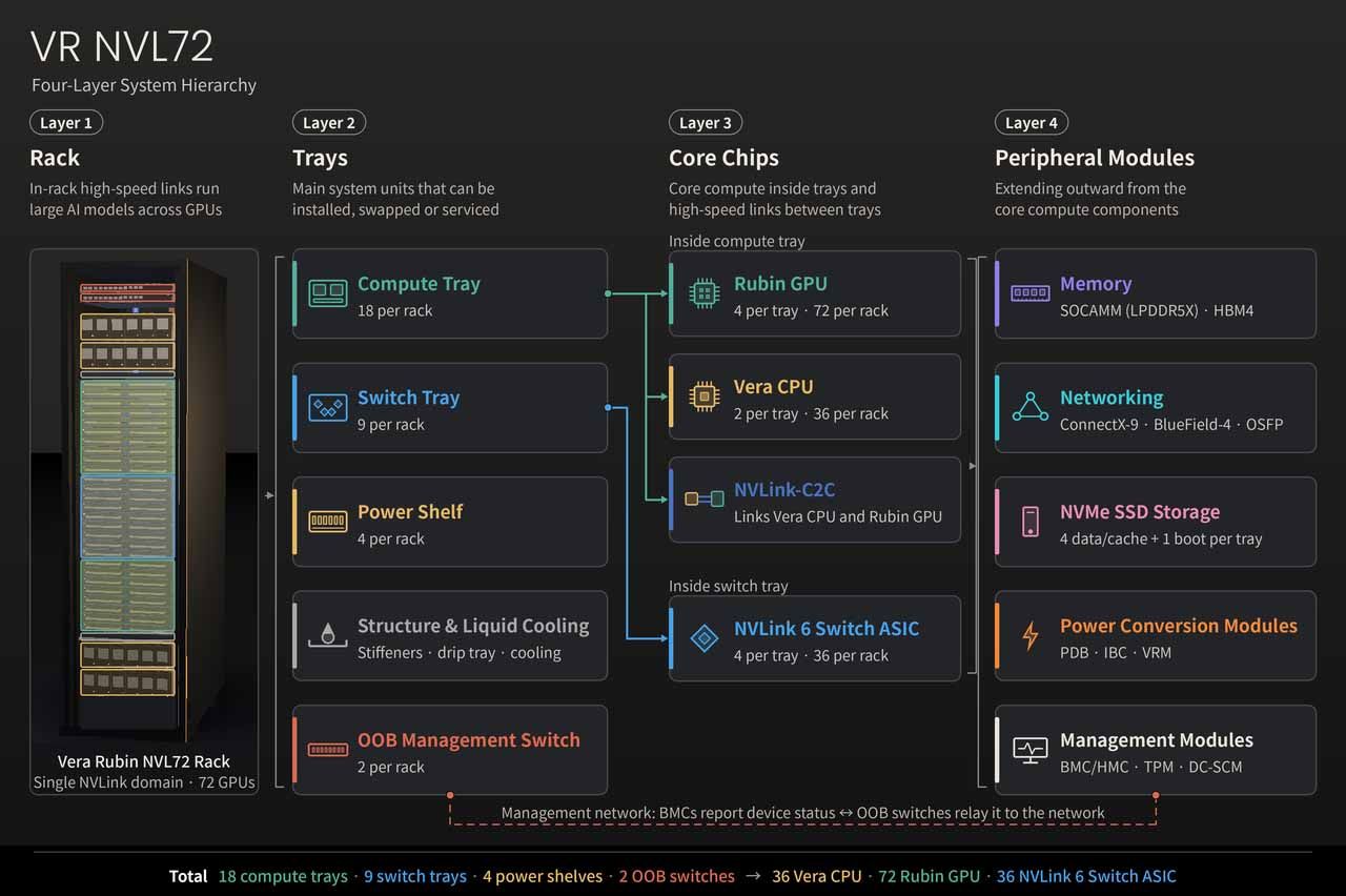
This article focuses on the Vera Rubin NVL72 compute rack. The full Vera Rubin platform also includes external networking, storage, and other specialized compute racks. Here, we break down the rack into four layers — rack, trays, core chips, and peripheral modules — moving from the system level to individual components.
- Layer 1 – Rack: The rack is the first layer of the Vera Rubin NVL72 architecture. Its high-speed in-rack interconnects allow large AI models to run across multiple GPUs, distributing model weights, compute workloads, and intermediate results among GPUs for collaborative processing.
- Layer 2 – Trays: The second layer includes compute trays, switch trays, power shelves, out-of-band (OOB) management switches, and the rack’s structure and liquid cooling. Together, these form the main system units that can be installed, replaced, or serviced within the rack.
- Layer 3 – Core chips: The third layer includes Vera CPUs, Rubin GPUs, NVLink-C2C, and NVLink 6 Switch ASICs. These components handle core compute within each tray and high-speed interconnects between trays.
- Layer 4 – Peripheral modules: The fourth layer extends beyond the core compute components to cover memory, networking, storage, power conversion modules, and management modules.
High-Speed Interconnects Enable Coordinated Compute Across the Vera Rubin Rack
The rack is the first layer of the Vera Rubin NVL72 architecture. Its high-speed in-rack interconnects allow large AI models to run across multiple GPUs, distributing model weights, compute workloads, and intermediate results among GPUs for collaborative processing.
The Vera Rubin NVL72 uses a 48U MGX rack architecture. As shown in the diagram, 18 1U compute trays are arranged in two sections in the middle of the rack, with nine 1U NVLink switch trays in the center. The rack also integrates four 3U power shelves, two OOB management switches at the top, rack stiffeners, a drip tray, and liquid-cooling infrastructure.
Each compute tray contains two Vera Rubin Superchips. Each Superchip consists of one Vera CPU and two Rubin GPUs connected via NVLink-C2C. This gives each tray two CPUs and four GPUs, and the full rack a total of 36 Superchips, 36 CPUs, and 72 GPUs. A Superchip is an integrated compute unit in which the CPU and GPUs are closely interconnected; it is not a single die. Each Rubin GPU package also contains two primary compute dies, bringing the rack’s total to 144 primary GPU compute dies.
Each switch tray in the center of the rack contains four NVLink 6 Switch ASICs. The rack has 36 switch chips in total, forming the single NVLink domain that connects all 72 GPUs. Each compute tray also integrates LPDDR5X memory in SOCAMM modules for the CPUs, HBM4 memory for the GPUs, ConnectX-9 NICs, a BlueField-4 DPU, NVMe SSDs, and power conversion and management modules. At the rear of the rack, the NVLink copper backplane, power bus bars, liquid-cooling manifolds, and connectors support system interconnects, power delivery, cooling, and maintenance. This coordinated design enables high-density compute across the rack while supporting routine servicing.
Compute Trays, Switch Trays, and Power Shelves Form the Vera Rubin Rack
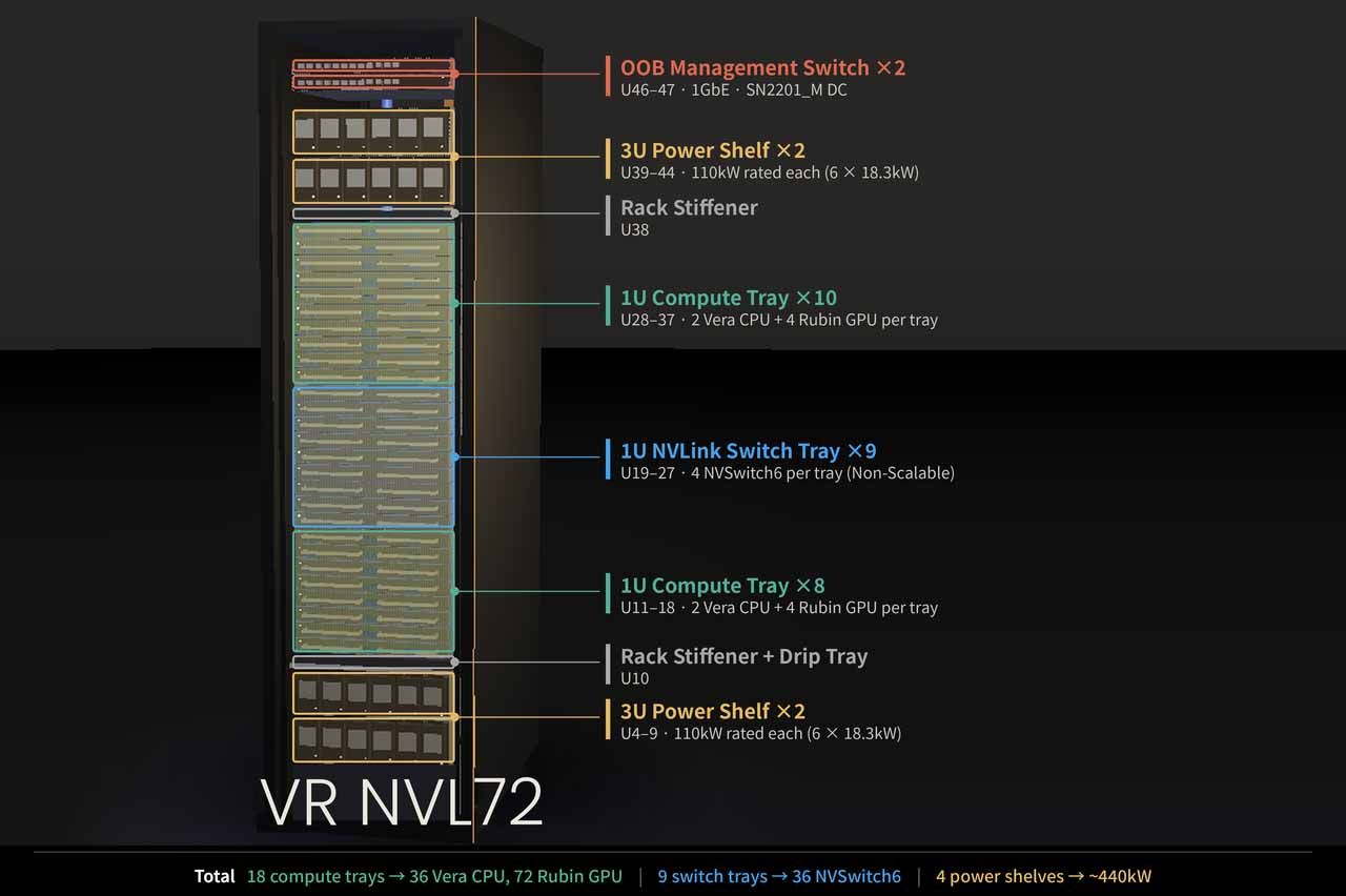
The second layer includes compute trays, switch trays, power shelves, OOB management switches, and the rack’s structure and liquid cooling. Together, these form the main system units that can be installed, replaced, or serviced within the rack. (This is a reference architecture; actual configurations may vary by OEM.)
| Second-layer unit | Configuration per rack | Primary function |
|---|---|---|
| Compute tray | 18 trays, 1U each | Houses CPUs, GPUs, memory, networking, and storage modules for compute |
| NVLink switch tray | 9 trays, 1U each | Connects the GPUs across all compute trays to form a single NVLink domain |
| Power shelf | 4 units, 3U each, rated at 110 kW | Converts incoming power into DC power for the rack |
| OOB management switch | 2 units | Carries hardware monitoring, firmware, and remote management messages |
| Structure and liquid cooling (rack stiffeners, drip tray, cooling system) | Distributed throughout the rack and trays | Supports and positions components, distributes coolant, and removes heat |
Compute Trays Integrate Two Superchips and Connect Compute to Peripheral Systems Through a Modular Design
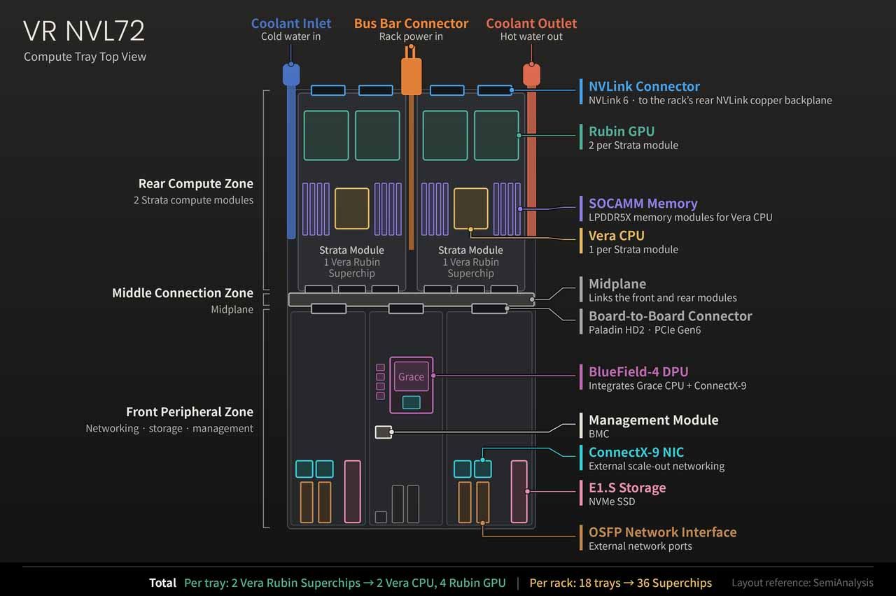
The compute tray houses the Vera Rubin NVL72’s main compute components. Each tray contains two Vera CPUs and four Rubin GPUs and can be divided, as shown in the diagram, into a rear compute zone, a middle connection zone, and a front peripheral zone.
The rear compute zone holds two Strata compute modules. Each module contains one Vera CPU, two Rubin GPUs, and associated memory. NVLink connectors and bus bar connectors at the rear connect the modules to the rack’s high-speed interconnect and power systems. In the middle connection zone, a midplane links the front and rear modules. The front peripheral zone integrates ConnectX-9 NICs, a BlueField-4 DPU, OSFP network interfaces, E1.S storage, and management modules. Coolant inlets and outlets on both sides of the tray support liquid cooling.
A compute unit consisting of one Vera CPU and two Rubin GPUs is called a Vera Rubin Superchip. Each tray therefore contains two Superchips, and all 18 compute trays in the rack contain 36 in total. A Superchip is an integrated compute unit in which the CPU and GPUs are closely interconnected; it does not combine three processors into a single die.
The modular plug-in design uses the midplane and board-to-board connectors to reduce the number of cables that must be installed individually inside the tray, making assembly and maintenance easier. The NVLink copper backplane at the rear of the rack and external network connections remain important parts of the system interconnect.
Switch Trays Integrate NVLink 6 Switch ASICs to Connect 72 GPUs at High Speed
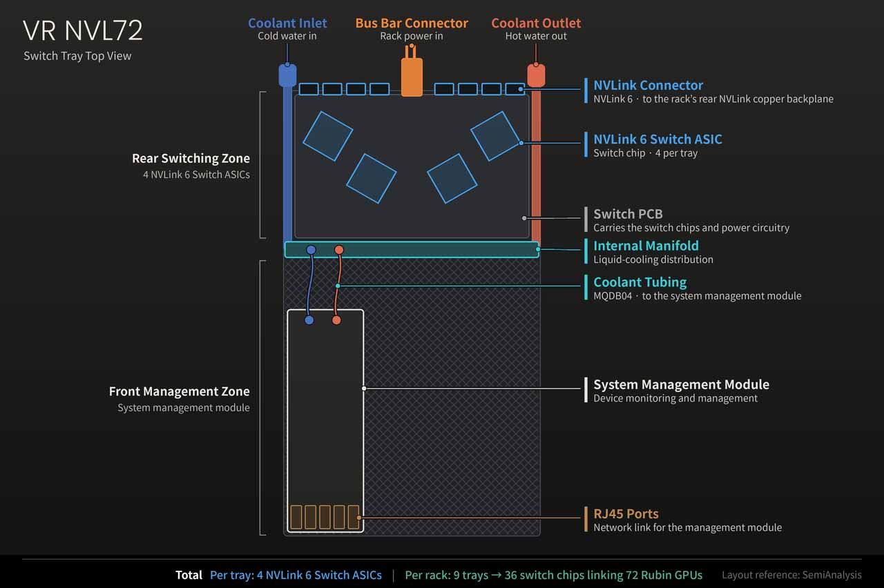
The switch tray handles data exchange between GPUs in the Vera Rubin NVL72 rack. Each tray contains four NVLink 6 Switch ASICs, for a total of 36 switch chips across the rack.
As shown in the diagram, the rear switching zone holds the main switching circuitry: the switch chips, the switch PCB, and associated power circuitry. NVLink connectors and bus bar connectors at the rear connect to the rack’s NVLink copper backplane and power system, respectively. Coolant inlets and outlets are located on both sides. An internal manifold, coolant tubing, and cold plates remove heat generated by the components. In the front management zone, a system management module monitors and manages the equipment.
GPUs in the compute trays connect to the switch chips through the NVLink copper backplane. Together, the switch trays form a single NVLink domain spanning all 72 GPUs, enabling compute trays to exchange model data and results. A switch tray is a serviceable system unit that integrates switching, power, management, and cooling components. The NVLink 6 Switch ASIC is the switch chip inside the tray that performs the actual data switching. The two sit at different levels: the tray is the system unit, and the ASIC is its core component.
Power Shelves Convert AC to 54V DC and Deliver Power to Each Tray Through Bus Bars
Power shelves handle rack-level power conversion. According to current DGX documentation, each shelf is rated at 110 kW and contains six PSUs rated at approximately 18.3 kW each. The PSUs convert 415–480V AC to 54V DC, which is then distributed to the trays through the rack’s power bus bars.
The rack contains four power shelves, for a total of 24 PSUs and a combined rated capacity of 440 kW. This figure represents the total capacity of the power equipment. Actual power consumption depends on the workload, power settings, and the load from other components; available power must also account for redundancy. Once power reaches a tray through its bus bar connector, power conversion modules step it down further to the operating voltages required by individual chips.
OOB Management Switches Connect Hardware Management Interfaces for Independent Monitoring and Remote Maintenance
Out-of-band (OOB) management switches connect the hardware management interfaces of devices in the rack. Through a separate management path, they support remote power control, temperature and voltage monitoring, firmware updates, and access to fault logs. As long as the management controllers and management network remain powered and operational, administrators can use this path to check equipment status and, if necessary, restart devices — even if the host operating system is unresponsive.
The two OOB management switches at the top of the rack connect to management controllers in the compute trays, the BlueField-4 DPUs, and the switch trays. They primarily carry messages needed for equipment monitoring and maintenance. Large volumes of AI compute data, by contrast, travel over NVLink or the scale-out compute network connected through ConnectX-9 NICs. OOB management switches and the NVLink network used by GPUs therefore have distinct roles and carry different types of traffic.
Cooling Spans the Rack, Tray, and Chip Levels, Combining Liquid and Air Cooling
The Vera Rubin NVL72 cooling system can be divided into three levels, from the rack down to the trays and chips.
- Rack level: Includes supply and return manifolds, tubing, and quick-disconnect couplings. These distribute coolant to each tray and carry heated coolant to an external coolant distribution unit (CDU). The rack-level system also includes liquid cooling for the power bus bars and fan-based air cooling for the power supplies.
- Tray level: Includes internal manifolds, coolant tubing, connectors, and integrated cold-plate modules within the compute and switch trays. These direct coolant to heat-generating components such as CPUs, GPUs, memory, NICs, and switch chips.
- Chip and component level: Includes chip heat spreaders, thermal interface material (TIM), cold-plate contact surfaces, and internal channels. Heat moves from the chips into the coolant through conduction and heat exchange. Air-cooled components transfer heat through thermal materials and heat sinks into the airflow, which carries it away.
| Level | Main cooling components | Function and coverage |
|---|---|---|
| Level 1: Rack | Supply and return manifolds, tubing, quick-disconnect couplings, liquid-cooled bus bar structures, PSU fans | Distributes and collects coolant from each tray and sends heat to the external CDU; also includes liquid cooling for power bus bars and air cooling for power supplies. |
| Level 2: Tray | Internal manifolds, coolant tubing, connectors, integrated cold-plate modules | Directs coolant within compute and switch trays to heat-generating areas, including CPUs, GPUs, memory, NICs, switch chips, and power components. |
| Level 3: Chip and component | Chip heat spreaders, TIM, cold-plate contact surfaces and channels, heat sinks | Transfers heat from chips and components into cold plates for removal by coolant. Air-cooled components transfer heat through thermal materials and heat sinks into the airflow. |
The Third Layer Integrates Core Chips and High-Speed Interconnects for Coordination Within and Across Trays
The third layer includes Vera CPUs, Rubin GPUs, NVLink-C2C, and NVLink 6 Switch ASICs. These components handle core compute within each tray and high-speed interconnects between trays. Vera CPUs and Rubin GPUs are housed in the compute trays. NVLink-C2C is the interface and communication protocol connecting the CPUs and GPUs. NVLink 6 Switch ASICs are housed in the switch trays and enable data exchange between GPUs in different compute trays.
Vera CPUs Handle System Control and Data Processing Alongside GPUs
Vera CPUs are housed in the compute trays and handle system control, data processing, and a range of CPU workloads. Each tray contains two CPUs, for a total of 36 in the rack. Each Vera CPU features 88 NVIDIA-designed Olympus cores and supports 176 hardware threads. Across the rack, this amounts to 3,168 cores and 6,336 threads.
In an AI system, Vera CPUs handle data preprocessing, control program execution, workload scheduling, and I/O processing, while coordinating data exchange between CPUs and GPUs. The growth of agentic AI and reinforcement learning also increases CPU demand for tasks such as program compilation, tool calls, environment simulation, and result validation. If these steps become a bottleneck, GPUs may sit idle waiting for data or instructions, even when compute capacity is available. CPU processing capacity and interconnect efficiency therefore also affect overall system utilization.
Rubin GPUs Use a Dual-Die Design for Parallel Processing and AI Matrix Acceleration
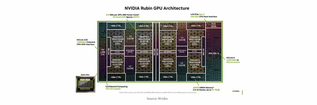
Rubin GPUs are also housed in the compute trays and handle large-scale parallel processing and AI matrix operations. Each Vera Rubin Superchip contains two GPUs, each compute tray contains four, and the full rack contains 72. Each Rubin GPU uses a dual-compute-die package connected through NV-HBI, integrating approximately 336 billion transistors, up to 224 streaming multiprocessors (SMs), and 896 Tensor Cores.
For performance, a single Rubin GPU delivers peak dense NVFP4 compute of 35 PFLOPS and peak sparse inference performance of 50 PFLOPS. Actual performance depends not only on peak compute but also on the speed at which memory supplies data and the efficiency of communication between GPUs. These factors together determine whether the GPUs can maintain high utilization.
NVLink-C2C Connects CPUs and GPUs, While NVLink 6 Enables Data Exchange Between GPUs
NVLink-C2C provides coherent interconnects between CPUs and GPUs, while NVLink 6 Switch ASICs handle data exchange between GPUs. NVLink-C2C connects Vera CPUs to Rubin GPUs and consists of interface circuitry on the processors, physical links, and a communication protocol. NVIDIA lists a bandwidth of 1.8 TB/s at the Vera Rubin Superchip level. In addition to high-speed data transfer, it provides coherent memory access, allowing CPUs and GPUs to use memory cooperatively and reducing the overhead of managing data exchange and synchronization. This links data processing and control flows with GPU compute.
NVLink 6 Switch ASICs are housed in the switch trays, with four per tray and 36 across the rack. When a model is distributed across multiple GPUs, these switch chips route data to the destination GPU and support model parallelism, expert routing, gradient exchange, and collective communication.
| Interconnect | Connected components | Role in the system |
|---|---|---|
| NVLink-C2C | Vera CPU ↔ Rubin GPU | CPU–GPU coordination, data exchange, and coherent memory access |
| NVLink 6 | Rubin GPU ↔ NVLink 6 Switch ASIC ↔ other Rubin GPUs | Forms a single NVLink domain for all 72 GPUs in the rack |
The Fourth Layer Covers Memory, Networking, Storage, Power Conversion, and Management Modules
The fourth layer extends beyond the core compute components to cover memory, networking, storage, power conversion modules, and management modules. HBM4 is integrated into the GPU package, while LPDDR5X is installed in SOCAMM modules next to the CPU. Other components are primarily distributed across boards and peripheral modules inside the trays.
| Component | Physical location | Quantity in the reference configuration |
|---|---|---|
| LPDDR5X for Vera | SOCAMM modules on the Strata compute module | 8 modules per CPU, 288 in the rack |
| HBM4 for Rubin | Inside the GPU package | 8 stacks per GPU, 576 in the rack |
| Host NVMe SSDs | Data/cache and boot drive bays in the compute trays | 4 + 1 per tray, 90 bays in the rack |
| Standalone ConnectX-9 NICs | Network modules at the front of the compute trays | 8 per tray, 144 in the rack |
| BlueField-4 DPU | DPU module at the front of the compute tray | 1 per tray, 18 in the rack |
| Power conversion modules | Power distribution board (PDB) and functional boards | PDB, IBC, and VRM, depending on board configuration |
| Management modules | Compute trays, switch trays, and other device modules | Distributed BMC/HMC, TPM, DC-SCM, and other management and security components |
LPDDR5X and HBM4 Meet the Capacity Needs of CPUs and the High-Bandwidth Needs of GPUs
LPDDR5X and HBM4 are the types of memory used by Vera CPUs and Rubin GPUs, respectively. They differ in configuration, capacity, bandwidth, and serviceability. LPDDR5X is a memory technology specification, while SOCAMM is the replaceable module that houses the memory; the two terms classify memory in different ways.
According to the configuration shown in the attachment, each Vera CPU is paired with eight SOCAMM modules, four on each side of the CPU. These modules store programs, workload data, and runtime state. The memory can also support workloads that require greater capacity through the CPU–GPU interconnect. Each Vera CPU supports up to approximately 1.5 TB of memory capacity and up to 1.2 TB/s of bandwidth. Across the rack, CPU memory capacity reaches up to approximately 54 TB. The replaceable module design can also limit the scope of replacement when memory fails.
HBM4 is high-bandwidth memory integrated into the Rubin GPU package, close to the compute dies. Its stacked memory and wide interface enable high-speed data transfer. It primarily stores model weights, intermediate compute results, and the KV cache used for inference. According to the configuration shown in the attachment, each Rubin GPU has eight HBM4 stacks, with 288 GB of memory capacity and 19.2 TB/s of bandwidth. Across the rack, total capacity is approximately 20.7 TB.
Capacity determines how much of a model and its workload data can be held in memory; bandwidth determines how quickly data can be supplied to the GPU. When a GPU repeatedly accesses model weights and the KV cache, HBM4’s ability to supply data directly affects how long compute units spend waiting and how efficiently they are used. Because HBM4 is part of the GPU package, its servicing and replacement differ from those of replaceable SOCAMM modules.
NVMe SSDs Provide Persistent Storage Within the Trays
NVMe SSDs provide non-volatile storage within the compute trays. NVMe is a storage communication protocol, while E1.S is an SSD form factor. In the current configuration, each compute tray has four data/cache SSD bays and one host boot SSD bay — 72 data/cache bays and 18 boot bays across the rack, for a total of 90 host SSD bays.
The boot SSD stores the operating system and related software, while data/cache SSDs support local data staging, model loading, and caching. Compared with HBM4 and LPDDR5X, SSDs provide higher-capacity persistent storage but have higher access latency and lower bandwidth. SSDs, CPU memory, and GPU memory therefore serve different storage and access needs, with software coordinating data movement between these tiers.
Power Conversion Modules Meet the Low-Voltage, High-Current Needs of Chips
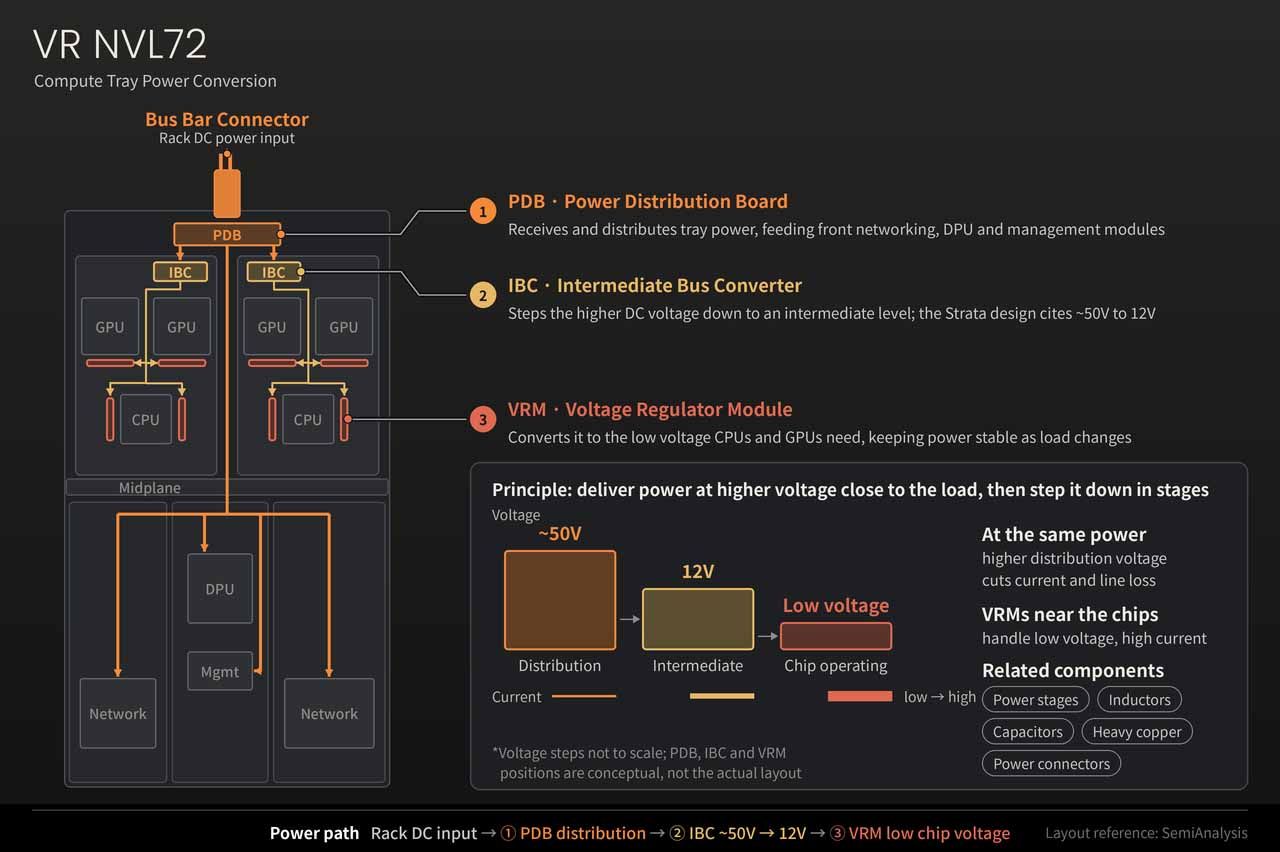
Power conversion modules convert the rack’s incoming DC power, delivered through the bus bar connector, to the operating voltages required by individual chips. Their main functions cover power distribution, intermediate voltage conversion, and point-of-load regulation:
- PDB (power distribution board): Receives and distributes power within the tray, supplying the networking, DPU, and management modules at the front of the tray.
- IBC (intermediate bus converter): Steps down the higher DC voltage to an intermediate voltage. The Strata design shown in the attachment describes a conversion from approximately 50V to 12V.
- VRM (voltage regulator module): Steps down the intermediate voltage to the low voltage required by CPUs, GPUs, and other components, while stabilizing power as loads change.
The underlying principle is to distribute power at a higher voltage and convert it closer to the load. At the same power level, a higher distribution voltage reduces current and line losses. VRMs near the chips then meet their low-voltage, high-current requirements. Power stages, inductors, capacitors, heavy copper layers, and power connectors work together to support power conversion and delivery.
Management Modules Support Equipment Maintenance Through the OOB Management Network
Management modules monitor hardware status, execute control functions, and establish a security trust mechanism. Controllers such as BMCs and HMCs in the compute trays monitor hardware, store event logs, and provide remote management interfaces. BMCs focus on hardware monitoring and control. TPMs provide security features such as key protection, integrity measurement, and trust functions. DC-SCMs integrate some management and security control functions into a module. Switch trays also have their own system management module with management and security components, so the rack management system is made up of controllers and modules distributed across the trays.
This layer connects directly to the OOB management switches. BMCs and other controllers collect equipment status and execute management commands, while the OOB management switches relay those messages to the management network. For example, when a tray detects an abnormal temperature, its management controller logs and reports the event so that the management system can diagnose it and schedule maintenance.
Conclusion
Breaking down the NVIDIA Vera Rubin NVL72 layer by layer — from the rack and trays to the core chips and peripheral modules — shows that coordinated rack-level operation is central to its design. Compute trays integrate CPUs, GPUs, and memory; switch trays form a single NVLink domain across all 72 GPUs; power and cooling systems sustain continuous operation under high-density loads; and management modules provide hardware monitoring, fault diagnosis, and remote maintenance.
Through close coordination across data transfer, power distribution, cooling, and management networks, these layers combine individual component functions into rack-scale AI computing capabilities.
