As AI model development shifts from training to inference, power consumption, package size, and thermal density of GPUs and ASIC chips are rising in tandem, driving a steady increase in chip TDP. If heat cannot be dissipated efficiently in real time, servers may experience frequent shutdowns, throttling, or even system instability.
Taking NVIDIA as an example, a single B300 chip already reaches a TDP of 1,400W. The Rubin architecture, expected in the second half of 2026, will further increase this to 2,300W, while the Rubin Ultra, planned for 2027, could exceed 3,000W per chip.
Against this backdrop, GPU server cooling architectures are rapidly shifting from traditional air cooling to direct liquid cooling. The latter has become the most important growth driver in today’s thermal management industry.
Technical Background: Cooling Advancements Still Fall Short
NVIDIA GPU Package and Server Rack TDP with Cooling Solutions
| Architecture | Ampere | Hopper | Blackwell | Blackwell Ultra | Rubin | Rubin Ultra | Feynman |
|---|---|---|---|---|---|---|---|
| TDP | 400W | 700W | 1200W | 1400W | 2300W | 3000W+ | 4000W+ |
| Cooling Solution | Air Cooling | Air Cooling | Direct Liquid Cooling (DLC) | DLC | DLC | DLC | Immersion Cooling |
| Deployment Timeline | 2020 | 2022 | 2024 | 2H25 | 2H26 | 2H27 | 2028 |
| Representative Products | A100 | H100/H200 | B200/GB200 | B300 | Rubin GPU | Rubin Ultra | Feynman GPU |
| Rack Architecture | GB200 NVL72 | GB300 NVL72 | VR200 NVL144 | ||||
| Rack TDP | 120–130kW | 130–140kW | <225kW | ||||
| Cooling Mix | Liquid (85%) + Air (15%) | Liquid (85%) + Air (15%) | Liquid (100%) |
Transitioning from Air Cooling to Liquid Cooling Still Struggles to Meet High-Power Demands
Traditional air cooling uses fans and airflow channels to remove heat. While the structure is simple and cost-effective, its cooling capacity is limited by airflow volume and fin surface area. This makes it less efficient in high power-density computing environments. As a result, air cooling is mainly suitable for low- to mid-power servers and struggles to support TDP levels above ~1,000W.
To enhance performance while retaining existing designs, the industry developed “liquid-to-air” cooling solutions. In this approach, heat from the chip is first transferred to air through heat sinks, then removed via a liquid-based heat exchanger that carries the heat into a water loop and out of the data center. Because water serves as the primary heat transfer medium, overall cooling capacity improves to support approximately 850–1,200W TDP. Its biggest advantage lies in high compatibility with existing server architectures, allowing data centers to upgrade cooling capacity without major hardware redesign. This makes it a key transitional solution in early AI data center upgrades. However, the presence of air in the heat transfer path remains a fundamental limitation, leading to inefficiencies and hotspot risks under high power loads. As such, liquid-to-air (L2A) is widely seen as a temporary solution, unable to support AI servers exceeding 1,200W TDP.
The current mainstream approach, “liquid-to-liquid” cooling, removes internal rack fans and uses coolant flowing through cold plates that directly contact the chip package. Heat generated by the chip is conducted through thermal interface materials (TIM) into the cold plate, then carried away by coolant to a Cooling Distribution Unit (CDU) and exchanged with the data center water system. This design keeps most heat within the liquid loop, significantly reducing thermal load on the rack.
While more efficient than air cooling, cold plate designs typically route coolant through channels at the base or sides, meaning heat must still pass through multiple interfaces such as the heat spreader and TIM layers. This creates a longer thermal resistance chain. As GPU power consumption rises beyond ~2,000W, interface resistance becomes a key bottleneck, pushing traditional single-phase cold plate solutions toward their limits.
| Technology Segment | Air Cooling | Liquid-to-Air | Liquid-to-Liquid |
|---|---|---|---|
| TDP | 500–1000W | 850–1200W | 1200–1500W |
| PUE | 1.5–1.7 | 1.07–1.3 | 1.07–1.3 |
| Advantages | Low cost, mature technology, easy maintenance | Hybrid cooling, high reliability | High efficiency, suitable for high thermal density |
| Disadvantages | Cannot support high power, noise issues | Higher cost, requires specialized maintenance | High initial cost, requires facility loop upgrades |
| Expected Commercial Timeline | Mature, gradually being replaced | Growth phase (2024–2027) | Mainstream (2025–2030) |
| Example Applications | AMD EPYC Genoa / Bergamo, NVIDIA A100 PCIe | High-performance servers, some AI workloads | NVIDIA DGX H100 / GB200 NVL |
Micro Channel Cold Plate (MCCP): Technical Overview

As traditional cold plates approach their physical cooling limits, the industry has begun adopting MCCP (Micro Channel Cold Plate) as an enhanced solution. Both share a similar packaging structure, consisting of four layers: TIM1, heat spreader, TIM2, and the cold plate. The key difference lies in the optimization of the internal flow channel design within the cold plate.
Traditional cold plates use macro-scale channels with widths of around 150 μm, limiting the contact surface area between coolant and metal walls. As a result, heat transfer efficiency is constrained by the fluid’s convective boundary layer, making it increasingly insufficient as AI chip power consumption rises. MCCP introduces a direct and effective improvement: without altering the overall packaging structure, it reduces channel width to 80–100 μm while increasing the number of channels. This significantly expands the total contact surface area between coolant and metal, effectively doubling heat transfer efficiency and supporting power demands of around 1.8 kW, such as those of the Vera Rubin R100.
The key to MCCP’s improved performance lies in its microfluidic engineering design. A closer look inside a microchannel cold plate reveals its thermodynamic core. After entering through the inlet, coolant is not simply passed through an empty cavity; instead, it is directed into precisely machined microchannels formed through high-precision metal processing.
The cooling structure is built on a metal base with excellent thermal conductivity, which is tightly attached to the heat-generating chip below. Above this base, engineers fabricate dense and parallel cooling fins using advanced machining techniques. The narrow gaps between these fins form the microchannels through which coolant flows.
From a fluid dynamics perspective, coolant enters from one end of the module and rapidly flows through the parallel microchannel array. The micro-fin design significantly increases the contact area between metal and liquid, enabling efficient forced convection to quickly carry away large amounts of heat conducted from the chip.
Micro Channel Lid (MCL): Technical Overview
MCCP Meets Current Needs, While MCL Targets Higher Power Challenges
The core value of MCCP lies in enabling rapid deployment with minimal architectural changes, making it a critical transitional solution before MCL reaches mass production. However, it does not resolve the fundamental bottleneck: TIM2, which has a low thermal conductivity of only 2–7 W/m·K and accounts for over 70% of total thermal resistance. As AI chips are expected to exceed 2,000W or even 3,000W beyond 2027, MCCP is approaching its performance ceiling.
| Thermal Layer & Material Type | Thermal Conductivity (W/m·K) | Physical Characteristics & Impact | Applications & Pain Points |
|---|---|---|---|
| Silicon chip (SoC, HBM) | 130–150 | Single-crystal structure with excellent phonon conduction | Extreme hotspots under high power |
| TIM1 (liquid metal, silver paste) | 40–80 | Very high conductivity, handles bare-die heat flux | Pump-out effect under thermal cycling, leading to voids and failure |
| Heat spreader (oxygen-free copper) | ~400 | Excellent conduction and heat spreading | Increases package size, weight, and thermal path length |
| TIM2 (thermal paste, phase-change material) | 2–7 | Low conductivity, provides surface contact and mechanical buffering | Highest thermal resistance layer, often >70% of total |
| Cold plate (metal) | 200–400 | Macro channels for convective heat exchange | Limited by fluid boundary layer |
The core bottleneck of this architecture lies in TIM2. Even high-end TIM2 materials have thermal conductivity of only 2–7 W/m·K, nearly 100 times lower than copper (~400 W/m·K). When TIM2 thickness reaches tens of microns, its thermal resistance contribution typically ranges from 0.1 to 1.0 °C·cm²/W.
In earlier generations, where chip TDP was only a few hundred watts, this level of resistance was manageable. However, with the sharp increase in localized heat flux in AI chips, even a TIM2 resistance of 0.1 °C·cm²/W can create temperature differences of up to 100°C across the interface. This significantly raises junction temperatures, easily exceeding the safe operating range of 80°C to 100°C, ultimately leading to throttling, failure, or system crashes.
As a result, both traditional cold plate-based direct liquid cooling and MCCP fundamentally face the same physical limitation: long heat transfer paths and heavy reliance on low-conductivity TIM2 as a critical interface. While MCCP improves overall cooling performance through microchannel optimization and enhanced convective heat transfer, it cannot bypass the thermal resistance bottleneck introduced by TIM2. As long as this interface layer remains, it is difficult for systems to truly overcome the cooling limits of high-power AI chips—this is precisely why the industry is moving toward the development of MCL architectures.
MCL Integrated Architecture Significantly Shortens the Thermal Path
| Layer (Top to Bottom) | Cold Plate DLC | MCCP | MCL |
|---|---|---|---|
| Coolant Circulation Layer | Cold Plate (macro channels ~150 μm) | Cold Plate (microchannels 80–100 μm) | Eliminated |
| TIM2 | Present | Present | Eliminated |
| Heat Spreader | Present | Present | Eliminated |
| Heat Exchange Core | Cold plate external to package | Cold plate external to package | Integrated via micro-channel lid |
| TIM1 | Present | Present | Remains |
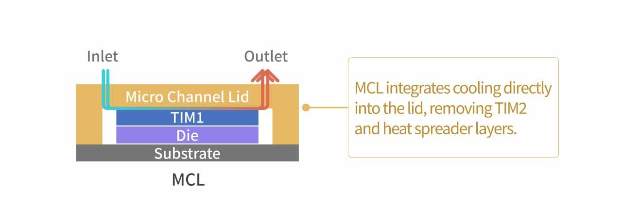
The MCL architecture removes TIM2, the heat spreader, and the cold plate in a single step, replacing them with an integrated micro-channel lid. This allows coolant to circulate directly within the lid closest to the chip, significantly shortening the heat transfer path and reducing overall thermal resistance. This design consolidates the functions of the heat spreader and cold plate into a single component—the micro-channel lid. Because cooling channels are built directly into the structure, it eliminates the critical thermal resistance bottleneck introduced by TIM2, making it a key technology for enabling next-generation AI servers to handle ultra-high power loads.
MCL Heat Transfer Path (bottom to top):
- Heat is generated by the chip (SoC & HBM).
- Heat is conducted to the first thermal interface material (TIM1).
- Heat enters the micro-channel lid directly, where coolant flows through channels adjacent to TIM1, rapidly removing heat.
According to current academic literature, lid-integrated microchannel cooling modules already have validated experimental data. Traditional MCCP systems show thermal resistance around 0.07 K/W, delivering roughly 50% better performance than macro-channel cold plates. For MCL, by eliminating TIM2 and the heat spreader, theoretical models suggest up to a 3× improvement over conventional direct liquid cooling, making it capable of supporting AI chips exceeding 2.3 kW.
| Metric | Data | Source |
|---|---|---|
| Thermal resistance (chip to coolant inlet) | 27.1 mm²·K/W | ScienceDirect, experimental data (flow rate 1 L/min) |
| Max temperature difference on chip surface | 6.3°C (measured) / 4.1°C (optimized simulation) | Same source, at 150 W/cm² heat flux |
| Pressure drop | 18.3 kPa (flow rate 1 L/min) | Same source |
| Microchannel dimensions | Depth 250 μm, width ~210 μm | Same source |
Vapor Chamber Expertise Becomes a Key Barrier for MCL Mass Production
Although MCL removes the traditional heat spreader at the hardware level, its functions—heat spreading and chip protection—are not eliminated but fully integrated into the micro-channel lid itself. This makes it one of the most critical and challenging aspects of the design. In conventional architectures, the heat spreader appears to be a simple metal cover, but it plays two essential roles: protecting the fragile silicon die and evenly distributing localized hotspots.
It acts as the first line of defense against mechanical stress and thermal expansion cycles, while also leveraging high thermal conductivity to spread extreme hotspots generated by SoC and HBM during AI workloads. Without this function, concentrated heat would directly impact the cooling interface, reducing overall efficiency.
With MCL integrating both the lid and heat exchanger into a single structure, engineers must balance multiple competing requirements within an ultra-thin metal substrate. The material must provide strong heat spreading capability while also incorporating precisely fabricated microchannels (80–100 μm) to ensure uniform flow distribution and manageable pressure drop. At the same time, these fine चैनnels must not compromise structural integrity, as the component must withstand packaging stresses and tens of thousands of thermal cycles without deformation or failure.
Reliability presents an additional challenge. Long-term coolant flow through microchannels can lead to particle buildup and clogging. Unlike traditional cold plates, MCL cannot be replaced independently—failure may require scrapping the entire high-value AI chip. As a result, reliability standards are significantly stricter.
To mitigate clogging risks, filtration systems must be upgraded to below 10 μm. However, upgrading CDU filtration to this level increases system pressure drop, pump power consumption, and maintenance frequency. This highlights that as cooling architectures evolve toward MCL, filtration upgrades become a necessary parallel development.
Overall, any imbalance in these design factors can lead to lower yields or product failure. This explains why MCL development cycles are significantly longer than traditional cold plates and why yield remains a major bottleneck for mass production.
Against this backdrop, long-established vapor chamber technologies are gaining renewed importance in the transition to MCL. Manufacturers with deep expertise in vapor chamber production possess four key engineering capabilities that serve as critical entry barriers to MCL mass production:
- Metal material properties: Including thermal expansion of oxygen-free copper, fatigue behavior under repeated thermal cycling, and compatibility with various TIM materials—directly applicable to MCL lid design and reliability.
- Electroplating process control: Ensuring uniform, dense coatings with strong adhesion to prevent delamination. MCL microchannel walls require similar precision plating for corrosion resistance and thermal performance. This becomes even more critical with new TIM2 materials (e.g., graphite/indium composites) that may corrode lid surfaces.
- Packaging structural mechanics: Understanding stress from substrate warpage, die bonding, and assembly forces. MCL introduces added complexity due to integrated flow channels and increasing chip sizes.
- Hotspot diffusion design: The ability to evenly distribute localized heat within a limited area—essential for maintaining overall cooling efficiency in MCL systems.
Key Beneficiaries
Jentech Precision (3653.TW)
Company Overview
Jentech, originally focused on precision molds and electronic components, has transitioned toward high-end thermal solutions. Its core products include advanced vapor chambers, LED lead frames, and automotive IGBT cooling modules, while also offering one-stop customized thermal solutions integrating CPU retention modules, vapor chambers, and liquid cooling plates. The company possesses vertically integrated capabilities spanning mold development, stamping, and semiconductor-grade electroplating surface treatment.
As of 2025, thermal-related products account for 73% of total revenue, serving as the primary driver of both revenue and profitability. Its major clients include leading global foundries, OSATs, and chip designers such as Taiwan Semiconductor Manufacturing Company (TSMC), ASE Technology Holding, Advanced Micro Devices (AMD), Intel, and NVIDIA. The top customers collectively contribute over 70% of revenue. Its liquid cooling plate products have also entered the supply chain of server system providers such as Super Micro Computer, Inc. (Supermicro).
Competitive Advantages: Cross-Disciplinary Strength in Packaging Design, Precision Manufacturing, and Electroplating
As liquid cooling technology continues to evolve, suppliers must integrate expertise in both mechanical engineering and semiconductor packaging. Jentech has already penetrated the supply chain for NVIDIA GPU vapor chambers and TSMC’s CoWoS packaging components, including lids and stiffeners. It has accumulated hands-on experience in early-stage chip design participation, covering geometry specifications, material selection, and interface definition.
From an MCL development perspective, Jentech holds a competitive edge through its packaging design capabilities, large-scale electroplating production capacity, and long-standing customer relationships. Given the higher requirements for electroplating precision and structural mechanics in MCL mass production, Jentech is well-positioned to extend its precision stamping expertise to meet microchannel fabrication demands, strengthen yield control through vertically integrated plating lines, and leverage its CoWoS experience to address more complex structural challenges.
| Key MCL Process Barrier | Jentech Capability | Source of Capability |
|---|---|---|
| Microchannel etching precision | Precision stamping + thin-wall vapor chamber manufacturing | 30+ years of vapor chamber production |
| Electroplating yield control | In-house plating lines with expertise in copper uniformity | Vertically integrated plating process |
| Packaging structural mechanics | Core supplier of TSMC CoWoS lid/stiffener | Long-term packaging collaboration |
| Hotspot diffusion design | Core vapor chamber design capability transferable to MCL | Internal R&D expertise |
| Early-stage design involvement | Participates in every NVIDIA GPU generation from early design | Strategic supplier positioning |
Growth Driver 1: Rubin Platform Upgrades Drive ASP Expansion and Lay Foundation for MCL
MCL is expected to begin contributing meaningful revenue between 2H27 and 2028. Before that, the Rubin generation (launching in 2H26) represents a transitional phase toward liquid-integrated thermal solutions, with significantly higher specifications, manufacturing complexity, and pricing.
Rubin adopts a dual-die design, increasing package size. The stiffener must meet stricter requirements to prevent warping and cracking under thermal cycling, driving higher pricing. Additionally, due to new TIM2 material characteristics, the lid is upgraded to a dual-piece design with gold electroplating protection, further increasing ASP compared to the Blackwell generation. The technical requirements of Rubin’s dual gold-plated lid—particularly in plating precision, surface treatment, and structural design—are closely aligned with future MCL manufacturing, making this a critical stepping stone for Jentech.
| Timeline | Product | Relative ASP | Visibility |
|---|---|---|---|
| Current | B300 vapor chamber (graphene) | Baseline (USD 20–25) | In mass production |
| 2H26 | Rubin stiffener + dual gold-plated lid | Multiple increase (stiffener USD 20–30) | Volume ramp in 3Q26 |
| 2027 | CPO stiffener (Spectrum-5 / Q5) | USD 30–60 per unit | Design confirmed |
| 2H27–2028 | Micro-channel lid (MCL) | 7–10× current solutions | Design pending |
Growth Driver 2: Expansion into CPO and Automotive Cooling
Beyond AI-related business, Jentech is extending its structural packaging expertise into the co-packaged optics (CPO) sector and is expected to become a key supplier of stiffeners for NVIDIA Spectrum-5 and Quantum-5 switch chips. This segment is projected to contribute around 10% of revenue by 2027, highlighting the company’s ability to address both computing and networking markets.
Meanwhile, approximately 16% of revenue comes from non-AI segments, particularly automotive IGBT cooling modules. This business benefits from rising global electric vehicle adoption, providing a relatively stable revenue stream independent of AI industry cycles.
MGC (7892.TW)
Company Overview
MGC, founded in 2022, focuses on liquid cooling equipment and system integration solutions. Its core products include CDUs (Cooling Distribution Units), Sidecar units, and customized system integration (SI) project services, primarily targeting secondary-side infrastructure in data centers and server rooms. Following capital expansion, the company’s paid-in capital reached NT$469 million, and it was listed on the Emerging Stock Market on January 16, 2026, at a reference price of NT$238. Its major clients include Foxconn subsidiary Ingrasys, Wistron, and Wiwynn, as well as IC design firms such as Realtek, Silicon Motion, and Alchip for lab and data center build-outs.
Competitive Advantage 1: Early Positioning in CDU and Sidecar with Cost and Product Development Edge
MGC’s competitive strength lies in its positioning at the core of the transition from hybrid cooling to full liquid-to-liquid architectures. As server rack power density continues to rise, cooling solutions are evolving from liquid-to-air approaches (such as rear-door heat exchangers and Sidecar units) toward CDU-centric liquid-to-liquid systems. At the same time, the adoption of direct liquid cooling and MCL technologies significantly improves chip-level heat transfer efficiency, but also raises system-level requirements for coolant circulation, heat exchange efficiency, and overall stability.
By offering both Sidecar and CDU products, MGC is well positioned to capture this system-level upgrade trend, establishing itself as a key equipment supplier within the liquid cooling ecosystem. CDUs are among the highest-value components in liquid cooling systems, typically priced between USD 50,000 and 150,000 per unit. As system capacity scales from 600kW and 1.3MW to 2.5MW and eventually 4MW, both pricing and technical barriers continue to rise, creating a strong volume-and-price growth trajectory.
Compared to global peers, MGC holds a cost advantage of approximately 15%–20%, strengthening its competitiveness and market share expansion. The company is also actively developing new products such as negative-pressure CDUs, further reinforcing its growth outlook over the next three to five years.
Competitive Advantage 2: Integrated Equipment Manufacturing and System Solutions
| Upstream | Midstream | Downstream |
|---|---|---|
| Land, infrastructure providers | Data center design & construction, server room planning, rack products, cybersecurity, facility management MGC (7892.TW) | Server rooms, data centers, ODMs and branded server vendors |
Another key advantage of MGC is its dual capability in equipment manufacturing and data center system integration, rather than being solely a hardware supplier. This business model allows the company to expand from selling individual products to delivering full data center planning and construction projects, increasing the total value per customer engagement.
When MGC undertakes a data center project, it not only recognizes engineering revenue but also drives bundled sales of CDU and Sidecar equipment, forming a one-stop solution that enhances both revenue scale and customer stickiness.
As cooling technologies evolve from system-level liquid cooling to package-level MCL, the importance of fluid dynamics, pressure control, heat exchange efficiency, leakage risk management, and overall system stability continues to increase. This trend favors vendors capable of delivering integrated solutions. In addition to CDU equipment, MGC provides secondary-side system integration covering equipment, piping, and full data center planning. As MCL adoption increases system complexity, the value of MGC’s integrated capabilities is expected to grow further.
Growth Driver 1: MCL Drives Filtration Upgrades
As MCL reduces coolant channel dimensions to around 80 μm, it significantly improves cooling efficiency but also increases the risk of clogging. Over time, particle accumulation can reduce effective heat transfer area, degrade cooling performance, and worsen chip temperature distribution, ultimately impacting performance and lifespan.
Currently, most CDU-integrated filtration systems in data centers are rated at 50 μm, with optional upgrades typically reaching only 25 μm—still insufficient for MCL requirements. To protect 80 μm microchannels and minimize long-term clogging risks, filtration capability must be improved to below 10 μm.
MGC addresses this need with its external filtration systems capable of filtering coolant impurities down to 10 μm. These solutions effectively reduce contamination buildup while balancing pressure drop and cost, thereby extending the lifespan and reliability of liquid cooling systems.
